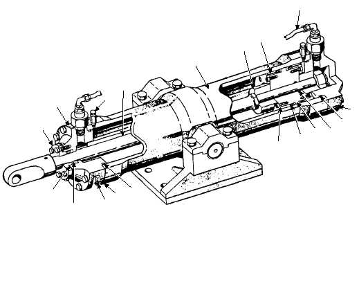
glands (11) secured by bolts, each safety wired. Shims
(14) are provided between the piston face and piston
gland to obtain the proper packing float. The piston rod
is sealed where it extends through the front cap (3) by
four V-ring packings (12), a spacer, and piston rod
gland (10) secured by bolts and washers. Shims (14) are
provided to obtain proper packing float. A terminal is
attached to the end of the piston rod and is secured by a
setscrew. The front cap and rear face are each fitted with
a tailpiece, an adapter, an orifice plate, a union nut, and
an elbow to attach hose; joints are sealed by O-rings
and packing. A vent valve assembly (8) and plug (9) are
located at each end of the hydraulic cylinder to vent air
or drain fluid.
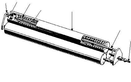
COUNTERBALANCING SPRING
The counterbalancing spring supplements the force
of the stanchion cylinder in raising the stanchion, and
cushions the contact of the stanchion with the deck.
The counterbalancing spring (fig. 3-42) is a group
of three compression spring units (5) comprising five
3-40
14
12
9
13
13
14
12
1
13
13
4
7
11
6
2
5
8
3
10
1. PISTON
2. CYLINDER
3. FRONT CAP
4. REAR CAP
5. PISTON ROD
6. PLUNGER
7. HOSE
8. VENT VALVE ASSEMBLY
9. PLUG
10. PISTON ROD GLAND
11. PISTON GLAND
12. PACKING
13. 0-RING
14. SHIM
ABEf0341
Figure 3-41.—Hydraulic cylinder assembly.
1
2
3
4
6
7
5
1. EQUALIZING PLATE
2. CLEVIS
3. ROD
4. SPRING
5. COUNTERBALANCING SPRING UNIT
6. TERMINAL
7. CABLE
ABEf0342
Figure 3-42.—Counterbalancing spring assembly.