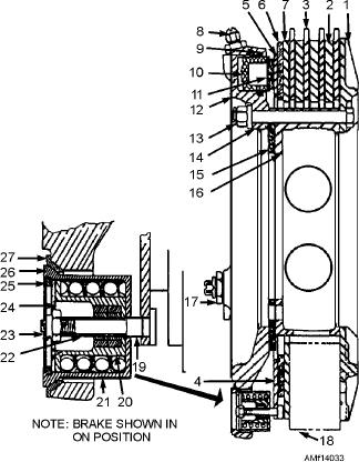
1.
Housing backplate
10.
Piston
19.
Self-adjusting pin
2.
Stationary discs
11.
Piston insulator
20.
Return-spring guide
3.
Rotating discs
12.
Brake housing subassembly
21.
Return spring
4.
Pressure plate subassembly
13.
Self-locking nut
22.
Self-adjusting pin tube
5.
Pressure plate
14.
Brake assembling bolt
23.
Self-locking nut
6.
Wear plate insulator
15.
Torque tube spacer
24.
Split collar grips
7.
Wear plate
16.
Keyed torque tube
25.
Retaining ring
8.
Bleeder valve
17.
Inlet bushing
26.
Spring housing
9.
O-ring and backup ring
18.
Self-adjusting mechanism
27.
Spring housing bushing
Figure 14-33.--Trimetallic brake assembly--cross section.
against the discs and against the housing backplate. As
discs. When pressure is removed from the brake, the
return springs return the pressure plate and the brake
the pressure is applied and the brake starts to actuate,
pistons to the designed reset clearance and maintain a
the lateral movement of the pressure plate
constant displacement.
subassembly pulls the self-adjusting pins, the split
collar grip and tube subassemblies, and the return
Maintenance
spring guides against the return springs, compressing
them until the spring guides bottom in the housings.
Intermediate maintenance of the trimetallic brake
When the hydraulic pressure is relieved, the return
assembly consists of disassembly, cleaning and
spring mechanisms, acting through the heads of the
inspection, wear pad replacement as necessary,
self-adjusting pins, pull the pressure plate
reassembly, and testing.
subassembly back to the released position. The pistons
DISASSEMBLY.--Place the brake assembly
also return to their deactuated positions. The extent of
with the brake housing down and remove the brake
the return motion is limited by engagement of the
housing bolts. Remove the backing plate and all discs
spring guides with the retaining ring stops inside the
spring housing.
Turn the brake over and remove the self-locking nuts to
As the discs wear, self-adjusting pins and tubes are
release the return pins. Remove the tube and grip
pulled through the split collar grips by the force exerted
assemblies, pressure plate, and the remaining return
on the pressure plate by the pistons. This small
spring parts. The tube and grip assemblies should not
movement of the adjusting pins and tubes, relative to
be disassembled. If they require replacement, replace
the grips, is equivalent to the combined wear of all the
the complete assembly as a unit.
14-35

