
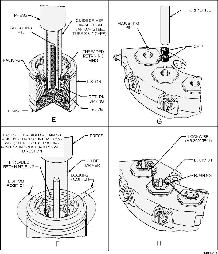
Figure 14-31.--Seal replacement and piston return adjustment--Continued.
TRIMETALLIC DISC BRAKES
functions properly. The brake discs should be free
when hydraulic pressure is released. Allow the brake
Figures 14-32 and 14-33 show a typical trimetallic
to stand for 2 minutes with pressure released and check
brake assembly. The trimetallic brake assembly
for static fluid leakage.
consists of a brake housing subassembly, a keyed
If the brake assembly is not to be installed
torque tube and torque tube spacer, a housing
immediately, install any attaching hardware that is part
backplate, stationary and rotating discs, and a pressure
of the assembly, fill with preservative hydraulic fluid,
and cap or plug all openings to prevent contamination.
plate subassembly.
14-33