
When a temperature is encountered that is lower than
control column or stick is moved to its extreme limits,
that at which the aircraft was rigged, the cables become
you can read the corresponding degree indication on
slack because the aircraft structure contracts more than
the throwboard. If the travel of the control surface is
the cables. When temperatures higher than that at
out of limits, you should adjust cables, push-pull rods,
which the aircraft was rigged are encountered, the
and control limit stops to obtain the correct control
aircraft structure expands more than the cables and
surface travel. When you are inspecting and rigging
tension is increased.
control surfaces, the specific maintenance instructions
manual should be consulted.
The cables in any cable linkage system are rigged
according to a temperature chart that is contained in the
Cable and Rigid Control System Rigging
applicable maintenance instructions manual. This
chart will give the proper tensions for the various
In the elevator system shown in figure 16-26,
temperature changes above and below the temperature
r i g g i n g b eg i n s a t t h e a f t s e c t o r. T h e a i r c r a f t
at which the system was rigged.
manufacturer has determined the position of the aft
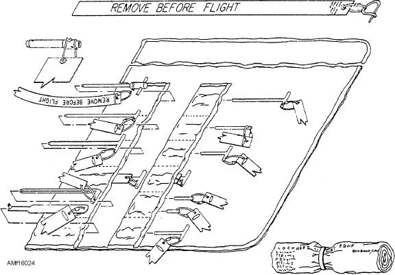
RIG PINS.Rig pins are used in rigging control
sector when it is in the neutral position. A rig pin hole
has been furnished in the sector and a mating hole in
systems. Figure 16-24 shows a rigging pin kit used on
the adjoining structure. See the three rig pins in figure
one of the Navy's aircraft. As you can see, rig pins may
16-26. With the rig pin inserted in the aft sector and in
come in various sizes and shapes and may be designed
the aircraft structure, the sector is held firmly in the
for one or many installations. You should refer to the
neutral position. With the sector in this position, the
specific maintenance instructions manual for use and
selection of rig pins.
push-pull tube connecting the sector with the elevator
fitting assembly is adjusted to position the elevators to
THROWBOARDS.Throwboards are special
the neutral position. The neutral position is determined
equipment used on specific aircraft for accurate
by using the elevator rigging fixture shown in figure
measurement of control surface travel. See figure
16-27. The curved section of the rigging fixture is
16-25. Each throwboard has a protractor scale that
graduated in degrees on either side of the neutral (zero
indicates a range of travel in degrees. Zero degrees
degree) position that is about midway on the curved
normally indicates the neutral position of the control
part of the fixture.
surface. When the throwboard is mounted and the
The rigging fixture is fastened securely to the
control column or stick is in neutral, the trailing edge of
aircraft at the indicated points of attachment. When
the control surface should be aligned to zero. As the
Figure 16-24.--Rigging pin set.
16-29