
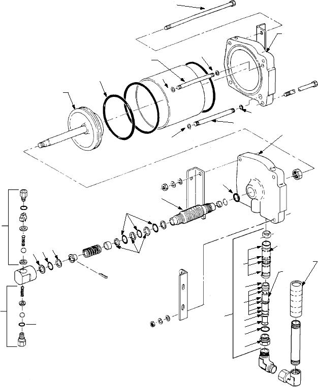
BARREL
UPPER
CAP ASSY
O
FLOW TUBE
O
O
PISTON
O
FLOW TUBE
LOWER
O
CAP ASSY
O
BODY
O
OUTLET
CHECK
VALVE
ASSEMBLY
B4
SLEEVE
B4 O
B4
O
SPOOL
O
INLET
O
CHECK
CONTROL
VALVE
VALVE
ASSEMBLY
O
ASSEMBLY
O
O
O
O = O-RING
B4 = BACKUP RING
ASf0908
Figure 9-8.--Motor and pump assembly.
Operation
NOTE: The number in parenthesis following the
component name refers to figures 9-5 and/or 9-6.
The A/M26U-4 nitrogen servicing unit is used to
RECHARGE VALVE.--The recharge valve (9)
service high- and low-pressure nitrogen systems in
controls the flow of nitrogen from a facility source to
aircraft and support equipment. These systems
recharge the cylinders. The servicing hose from the
include, but are not limited to, struts, accumulators,
recharge facility attaches to the recharge connection
dampeners, reservoirs, high-pressure tires (over
(12). The recharge connection is capped when not in
50 psi), and fire-fighting equipment. The following is a
use. A check valve is installed in line with the recharge
general overview of the operating procedures for the
valve on the cylinder side to prevent reverse flow of
A/M26U-4. Complete and up-to-date operating
procedures are included in AG-750AO-OMM-000,
nitrogen.
9-11