
the axis in this instance being the rotor shaft
their J57 axial-flow turbojet engine. Since this
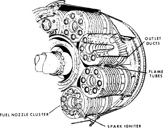
housing. Figure 1-28 shows this arrangement to
engine features the split-spool compressor, it
advantage.
requires combustion chambers capable of meeting
The combustion chambers are enclosed by a
the stringent requirements of maximum strength,
removable steel shroud, which covers the entire
limited length, and high overall efficiency. These
burner section. This feature makes the burners
attributes are necessary because of the high air
readily available for any required maintenance.
pressures and velocities present in a split-spool
The burners are interconnected by projecting
compressor, a l o n g with the shaft length
flame tubes, which help the engine-starting
limitations.
process in the can-type combustion chamber.
The split-spool compressor requires two
These flame tubes perform a function identical
concentric shafts joining the turbine stages to their
with those previously discussed, the only
respective compressors. The front compressor,
difference being in construction details.
joined to the rear turbine stages, requires the
Figure 1-28 also reveals that each of the
longest shaft. This shaft is inside the other. A
combustion chambers contains a central bullet-
limitation of diameter is imposed, so that the
shaped perforated liner. The size and shape of the
distance between the front compressor and the
holes are predetermined to admit the correct
rear turbine must be limited if critical shaft lengths
quantity of air at the velocity and angle required
are to be avoided. High torque is present if there
to control the flame pattern. Cutouts are provided
is a long shaft of small diameter.
in two of the bottom chambers for installation
Since the compressor and turbine are not
of the spark igniters. Notice in figure 1-28 how the
susceptible to shortening, shaft length limitation
combustion chambers are supported at the aft end
is absorbed by developing a new type of burner.
by matching outlet ducts in the turbine nozzle
The burner designers had to develop a design that
assembly.
would give the desired performance in much less
Figure 1-28 shows how the forward face of the
relative linear distance.
chambers presents size apertures that align with
The can-annular combustion chambers are
the six fuel nozzles of the corresponding fuel
arranged radially around the axis of the engine;
Figure 1-28.-Can-annular combustion chamber components and arrangement.
1-22