and nozzle diaphragm are three of the most
commonly used. The turbine nozzle vanes are
located directly aft of the combustion chambers
and immediately forward of the turbine wheel.
The function of the turbine nozzle is twofold.
First, after the combustion chamber has intro-
duced the heat energy into the mass airflow and
delivered it evenly to the turbine nozzle, it
becomes the job of the nozzle to prepare the mass
flow for harnessing of power through the turbine
rotor. The stationary vanes of the turbine nozzle
are contoured and set at such an angle that they
form small nozzles. They discharge the gas as
extremely high-speed jets. Thus, the nozzle
converts a varying portion of the heat and
pressure energy to velocity energy. It can then be
converted to mechanical energy through the rotor
blades.
The second purpose of the turbine nozzle is
to deflect the gases to a specific angle in the direc-
tion of turbine wheel rotation. Since the gas flow
from the nozzle must enter the turbine blade
passageway while the turbine is still rotating, it
is essential to aim the gas in the general direction
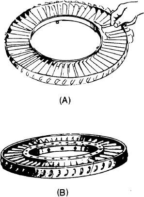
Figure 1-32.-Turbine nozzle vane assembly. (A) With loose
of turbine rotation.
fitting vanes; (B) with welded vanes.
The elements of the turbine nozzle assembly
consist of an inner shroud and an outer shroud,
between the nozzle vanes. The number of vanes
vanes could fall out of the shrouds as the shrouds
employed varies with different types and sizes of
are removed.
engines. Views A and B of figure 1-32 show typical
Another method of thermal expansion
turbine nozzles featuring loose and welded vane
construction is to fit the vanes into inner and outer
fits, respectively.
shrouds. However, this method welds or rivets the
The vanes of the turbine nozzle are assembled
vanes into position (fig. 1-32, view B). Some
between the outer and inner shrouds or rings in
means provide for the inevitable thermal
a variety of ways. Although the actual elements
expansion; therefore, either the inner or the outer
may vary slightly in their configuration and
shroud ring cuts into segments. These saw
construction features, there is one characteristic
cuts dividing the segments will allow enough
peculiar to all turbine nozzles; that is, the nozzle
expansion to prevent stress and warping of the
vanes are constructed to allow for thermal expan-
vanes.
sion. Otherwise there would be severe distortion
The rotor element of the turbine section
or warping of the metal parts because of rapid
consists essentially of a shaft and a wheel
temperature variances.
(fig. 1-31).
The expansion feature of the turbine nozzle
The following brief discussion of impulse and
is accomplished by one of several methods. One
reaction turbines should help clarify their
method has the vanes assembled loosely in the
function. The turbine blades are of two basic
supporting inner and outer shrouds (fig. 1-32,
types--impulse and reaction. Most aircraft
view A). Each of the vanes fits into a contoured
engines use a blade with both impulse and reaction
slot in the shrouds. They conform with the air-
sections. The impulse is usually at the base of the
foil shape of the vanes. These slots are slightly
blade.
larger than the vanes to give a loose fit. The inner
The impulse turbine can be defined as a
and outer shrouds are encased by an inner and
turbine that derives its rotation from the weight
an outer support ring, which give increased
and velocity of the air striking its blades. The
strength and rigidity. These supports also help
reaction turbine derives its rotation from the air
remove the nozzle vanes as a unit. Otherwise, the
1-24

