
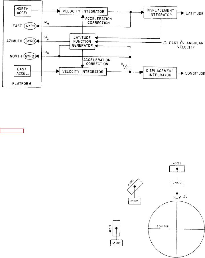
Figure 7-55.-Typical semianalytic inertial navagation system, block diagram.
resolved into the system axes. The system then
Geometric Inertial Navigation System
applies these signals to the gyro torquers. A
typical simplified block diagram of a semi-
The geometric INS uses a gyro system that,
analytic inertial navigation system is shown in
like the analytic system, is referenced to inertial
space in a nonrotating plane. The accelerometers,
In a semianalytic inertial system, the platform
however, mount on the gimbal structure in a
aligns normal to the gravity vector. It may or may
manner as to remain normal to the earth's
not align to true north. The output of the north
gravitational field.
accelerometer goes to an integrator. Here, the
output is summed with acceleration correction
terms to derive a true vehicular acceleration over
the earth's surface. This acceleration signal is then
integrated with respect to time, deriving the north
velocity component of the vehicle's track.
Through scaling, the INS converts the velocity
term to an angular velocity. It then integrates the
angular velocity to provide a position readout in
the form of latitude. In addition, the latitude
function generator uses the north angular velocity
signal to develop accelerometer correction terms.
It also uses this signal to develop a gyro torquing
signal for the east gyro.
The east accelerometer output is summed with
accelerometer correction terms and integrated to
provide an east component of the vehicle's track.
Through scaling, the INS converts the velocity
signal to an angular velocity. This angular velocity
function generator uses it to develop acceler-
ometer correction terms and torquing signals for
the north gyro and the azimuth gyro. In addition,
the INS integrates the angular velocity to develop
Figure 7-56.-Transport of the geometric system's stable
a position readout in the form of longitude.
element.
7-46