accelerometers mount at right angles, a motion
has accuracies to 10 seconds of arc. When using
about one axis causes the other to go through an
an inertial system as a source, the accuracies
angle with respect to the gravity vector. Therefore,
depend on its initial source and length of time
you connect the accelerometer output in a way
since last aligned. Such a method is usually for
to allow it to torque about its perpendicular axis.
mobile alignment where primary sources cannot
The accelerometer can now slew itself to a null
be used.
position, where it senses no component of gravity.
The use of an external reference system
As pointed out earlier, the device the system can
requires transfer devices to transmit the reference
torque about an axis is a gyro. In this case, the
information to the system. The transfer devices
gyro being torqued is the one sensitive about the
are either optical or electromechanical devices.
axis perpendicular to the accelerometer being
Optical devices include theodolites and auto-
leveled; that is, the Y gyro (north) torques the X
collimators; the electromechanical devices are
accelerometer (east) to level, etc.
synchro-resolver or digital type. Optical methods
The accelerometer will provide a dc voltage
can produce accuracies of a few seconds of arc.
that is proportional to the sine of the off level
The electromechanical methods are accurate to
angle. In the leveling mode, after amplification
about 30 seconds of arc.
this voltage goes to the gyro, whose sensitive axis
In self-alignment, the inertial sensing instru-
is perpendicular to the sensitive axis of the
ments mounted on the platform sense the deviation
accelerometer. (See fig. 7-52. ) In other words, the
from the desired position. To determine the
output of the X accelerometer goes to the Y gyro.
orientation of a three-axis orthogonal (perpen-
The output of the Y accelerometer goes to the
dicular) coordinate system, you must have at least
X gyro.
two noncollinear (not parallel) reference vectors.
For self-alignment, the earth's spin vector and the
mass attraction gravity vector serve this purpose.
Gyrocompassing
The self-alignment puts less requirements on the
computer. In self-alignment, the accelerometer
As mentioned, any gyro not having its spin
outputs don't have to be resolved into components
axis parallel to the earth's spin axis will apparently
of gravity and vehicle acceleration. When
precess about the earth. The rate at which it
accelerometers and gyros mount on the same
precesses is proportional to the angle between its
element, their relative position is fixed and does
spin axis and the earth's spin axis. This angle can
not have to be computed.
be resolved into two components. Since the gyro
Self-alignment often divides into two modes--
spin axis lies in the level plane already established,
rough or course alignment (sometimes called
one component can be found in the plane itself.
caging) and fine alignment. Fine alignment itself
Now, find the angle between the spin axis and a
divides into two modes--leveling and gyro-
vector in the level plane that intersects the earth's
compassing.
spin vector. Once you find these two angles, you
know the exact position of the platform axis.
Rough Alignment
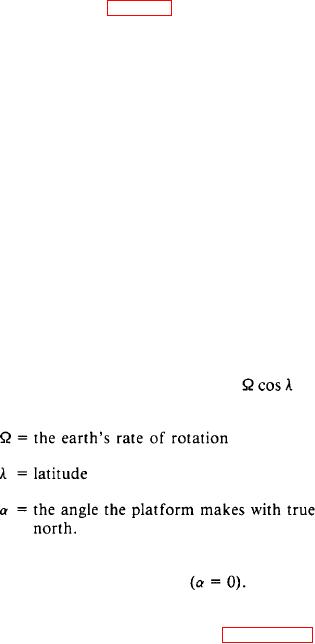
You can see the rate at which the gyro in
question appears to precess is equal to
sin
Rough alignment provides a convenient
a where
starting point for the later phases of alignment.
In most cases, the gimbals slave to their own
synchro outputs or to some external source. This
external source will have a particular orientation
with respect to the vehicle. A timing network
controls the duration of rough alignment, which
is usually a short period.
Fine Alignment (Leveling)
The spin axis of this gyro can be torqued to a place
where this term goes to zero
Also the
To accomplish fine alignment or leveling, the
computer can develop a torquing term equal to
system rotates the platform axes to the computer
this and apply it to the gyro. In either case, the
axes. For a locally level system, this is done by
placing the X and Y accelerometer axes mutually
shows a typical heading alignment loop.
perpendicular to the gravity vector. Since

