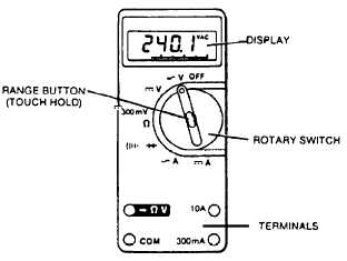
Figure 3-11.—A typical electronic multimeter.
precautions and requirements for quality assurance
verification.
Personnel involved in troubleshooting and per-
forming operational checks should consult the records
maintained in maintenance control and/or the work
center register. Reference to records of previous
maintenance may show a progressive deterioration of a
particular system or a previous discrepancy. This
procedure could be helpful in pinpointing the cause of
the malfunction currently being experienced.
ELECTRICAL FAILURES
Since practically all systems now have some
electrically controlled components, troubleshooting
must also include the related electrical circuits in many
instances. Although an AE is generally called upon to
locate and correct electrical troubles, you should be able
to check circuits for loose connections and even perform
continuity checks when necessary. Therefore, a
knowledge of electrical symbols and the ability to read
circuit diagrams is necessary. Figure 3-4 illustrates the
electrical symbols commonly found in schematic
diagrams.
Loose connections are located by checking all
connectors in the circuit. A connector that can be turned
by hand is loose and should be tightened hand tight.
A continuity check is simply a matter of
determining whether or not the circuit to the selector
valve, or other electrically controlled unit, is complete.
Continuity checks are made with the use of a multimeter.
The name multimeter comes from MULTIPLE
METER, and that is exactly what a multimeter is. It is a
dc ammeter, an ac ammeter, a dc voltmeter, an ac
voltmeter, and an ohmmeter, all in one package. Figures
3-10 and 3-11 show the faces of commonly used
multimeters. The applicable instructions should be
consulted prior to equipment operation.
TORQUING OF FASTENERS
Learning Objective: Recognize the importance
of the proper torquing of fasteners and the
required torquing procedures.
Fastener fatigue failure accounts for the majority of
all fastener problems. Fatigue breaks are caused by
insufficient tightening and the lack of proper preload or
clamping force. This results in movement between the
parts of the assembly and bending back and forth or
cyclic stressing of the fastener. Eventually, cracks will
progress to the point where the fastener can no longer
support its designed load. At this point the fastener fails
with varying consequences.
TORQUING PROCEDURES
For the nut to properly load the bolt and prevent
premature failure, a designated amount of torque must
be applied. Proper torque reduces the possibility of the
fastener loosening while in service. The correct torque
to apply when you are tightening an assembly is based
on many variables. The fastener is subjected to two
stresses when it is tightened. These stresses are torsion
and tension. Tension is the desired stress, while torsion
is the undesirable stress caused by friction. A large
percentage of applied torque is used to overcome this
friction, so that only tension remains after tightening.
Proper tension reduces the possibility of fluid leaks.
3-19