tires or wheels. The bead-breaking equipment shown
in figure 11-18 is available in two models. The Lee-I
model is designed for use at shore-based facilities.
The Lee-IX model is an explosionproof version of the
Lee-I, and is intended for shipboard use.
An example of the steps used for bead breaking
using the Lee-I equipment follows:
1. Ensure the tire is completely deflated.
2. Determine the type and size of the wheel to be
dismounted, and assemble the proper parts on the
drive shaft.
3. Push the outer centering rollers toward the
front of the machine, and roll the wheel (positioned
with the lockring side facing outward for
remountable flange wheels) on the outer centering
rollers. You should use the up and down push buttons
to raise or lower the drive shaft to the proper height
for the wheel being dismounted. Push the wheel onto
the drive shaft. If an open-rimmed tire assembly is
being dismounted, omit step 4 and proceed to step 5.
4. Insert the locking bar and turn it about 90
degrees counterclockwise. Mount the wheel cone on
the locking bar and insert the locking pin.
5. Push the air valve switch to the right. This will
clamp the wheel on the drive shaft.
217.182
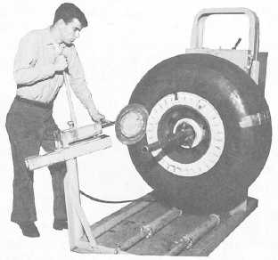
Figure 11-19.—Using bead-breaking pump.
6. Use the UP push button to raise the center of
the wheel to line up with the center of the bead-
breaking disc.
7. Rotate the tire by pushing the tire rotating
toggle to the right. Position the front bead-breaking
disc against the outside bead of the wheel flange. You
should adjust the position of the hydraulic pump
assembly by loosening the position lockpin and
sliding the pump to the proper position. After turning
the pump release valve clockwise as far as it will go,
apply hydraulic pressure against the bead by
pumping the handle, as shown in figure 11-19. Use
the guide handle to properly position the disc. Push
the bead back far enough to allow the removal of the
lockring or loose flange.
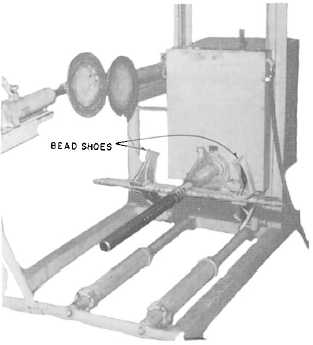
8. Remove the lockring and loose flange. You
should use the bead shoes to hold the bead back while
you are removing the lockring. See figure 11-20.
Release and retract the front bead-breaking disc by
turning the release valve counterclockwise.
9. Repeat the bead-breaking operation against the
rear surface of the tire with the rear bead-breaking
assembly.
217.183
Figure 11-20.—Shaft arranged to hold tire bead
while removing lockring.
11-20


