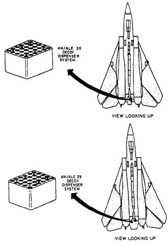
Figure 7-8.-Decoy dispenser configuration on aircraft.
disabled during jettisoning. The landing gear handle
must be in the UP position for all modes except
emergency.
F/A-18 AIRCRAFT WEAPONS SYSTEMS
The F/A-18 aircraft is a single seat, dual role
(fighter/bomber), supersonic aircraft. Provisions are
available in the aircraft for the application of external
power. The external power connector connects
115/200 volt, three-phase, 400-Hz ac power to the ac
bus. When external power is not available, there is an
auxiliary power unit (APU) to drive either of the
aircraft generators for functional checkout of the
aircraft systems.
The F/A-18 armament system consists of the
following systems and subsystems:
. F/A-18 armament basic controls and com-
ponents
l AN/AWW-4 fuze function control system
Rocket firing system
Walleye system
AN/AWW-7 data link system
AGM-65 Maverick fire control system
AGM-88 HARM fire control system
AIM-7 Sparrow fire control system
AIM-9 Sidewinder fire control system
M61A1 20-mm gun system
AN/ALE-39A decoy dispensing system
F/A-18 Armament Basic Controls and
Components
The F/A-18 armament system consists of the
following basic controls and components that are
common to all systems: the ground power control
panel assembly, the landing gear control handle, the
armament safety override switch, the master arm
control panel assembly, the aircraft controller grip
assembly, and the two digital display indicators.
GROUND POWER CONTROL PANEL
ASSEMBLY.— A ground power control panel
assembly provides four toggle switches, three of
which control the application of external power to
avionic and instrument systems. This prevents
excessive equipment operation time because of other
unassociated ground operations.
The EXT PWR switch is a three-position switch
that applies electrical power to the aircraft. In the
NORM position, electrical power is supplied to the
aircraft. In the OFF position, no power is supplied to
the aircraft. The RESET position resets power for the
external monitoring circuit when there is a temporary
overload. Switch 1 is a three-position switch with B
ON to provide enabling power to the mission
computers. Switch 2 is a three-position switch with B
ON to provide enabling power to the digital display
indicators (DDIs) and the radar. Switch 3 is
three-position switch with B ON to provide enabling
power to the armament computer, the AN/AWW-4
system, the HARM system, and the AN/ALE-39A
system.
7-5