
fastened, the units are securely bolted to the
manufacturer. If the misalignment is excessive,
foundation, and the coupling flanges are bolted
the coupling parts are subjected to severe punish-
together.
ment, necessitating frequent replacement of pins,
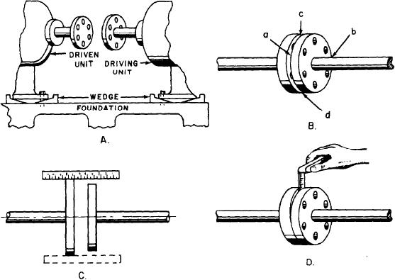
The faces of the coupling flanges should be
bushings, and bearings. It is absolutely necessary
checked at 90-degree intervals. This method is
to have the rotating shafts of the driving and
shown in figure 7-16, view B. Find the distances
driven units in proper alignment. Figure 7-16
between the faces at point a, point b (on the
shows coupling alignment.
opposite side), point c, and point d (opposite point
You should check the shaft alignment when
c). This action will show whether the coupling
the pump is opened for repair or maintenance,
faces are parallel to each other. If they are not
or if a noticeable vibration occurs. You must
parallel to each other, adjust the driving unit or
realign the unit if the shafts are out of line or
the pump with shims until the couplings check
inclined at an angle to each other. Whenever
true. While measuring the distances, you must
practicable, check the alignment with all piping
keep the outside diameters of the coupling flanges
in place and with the adjacent tanks and piping
in line. To do this, place the scale across the two
filled.
flanges, as shown in figure 7-16, view C. If the
When the driving unit is connected to the
flanges do not line up, raise or lower one of the
pump by a FLANGE COUPLING, the shafting
units with shims, or shift them sideways.
may require frequent realignment, which may be
The procedure for using a thickness gauge to
indicated by high temperatures, noises, and worn
check alignments is similar to that for a scale.
bearings or bushings.
When the outside diameters of the coupling
Wedges, or shims, are sometimes placed under
the bases of both the driven and driving units (fig.
flanges are not the same, use a scale on the
surface of the larger flange, and then use a
7-16, view A) for ease in alignment when the
thickness gauge between the surface of the smaller
machinery is installed. When the wedges or other
flange and the edge of the scale. When the
packing have been adjusted so the outside
space is narrow, check the distance between the
diameters and faces of the coupling flanges run
coupling flanges with a thickness gauge, as shown
true as they are manually revolved, the chocks are
Figure 7-16.--Coupling alignment.
7-12