
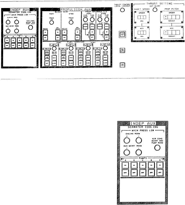
Figure 7-7.--A2 panel.
THRUST/AUXILIARY PANEL (A2)
stop the respective seawater cooling pump
from the PACC. The pumps are labeled left
to right #5, #4, #3, #2, and #1.
The operator uses this panel (fig. 7-7) to
control and monitor auxiliary and propulsion
auxiliary systems. For ease of explanation,
we will divide the panel into sections and
describe each section individually. These sections
are the INDEPENDENT AUX, PROPULSION
AUX, CONSOLE, THRUST SETTING, CON-
TROL LOCATION, and PROGRAMMED
CONTROL LEVER.
Independent Aux Section
This section is used to control and monitor
the seawater cooling system. It has five LEDs
and ten push buttons. The LEDs are used
to alert the operator when the seawater cooling
system pressure in a monitored space is at
or below its alarm set point. The spaces
monitored by these LEDs are engine rooms
#1 and #2, auxiliary machinery rooms #1
and #2, and the air conditioning machinery and
Propulsion Auxiliaries Section
pump room.
The operator uses this section of the panel to
The ten push buttons are five sets of
monitor and control the BLEED AIR (port and
starboard), PROP HYDRAULICS (port and
identical pairs. E a c h push button of the
starboard), and FUEL SERVICE (port and
pair is labeled ON or OFF, respectively.
starboard) systems.
These push buttons are used to start or
7-14