
console is operating on the emergency power
uses these push buttons to test the respective
source.
audible alarm. The rotary control switch is located
directly below these audible alarm test push
buttons. It is used by the operator to adjust the
volume of the audible alarms.
The two LEDs are located to the right of the
alarm test push buttons and are labeled TEMP
HIGH and UPS IN USE, respectively. The TEMP
HIGH indicator will illuminate amber to show
power supply temperature is excessive. The UPS
IN USE indicator will illuminate red to show the
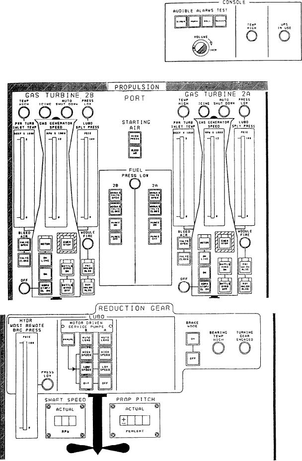
Figure 7-6.--A1 panel propulsion section.
7-10