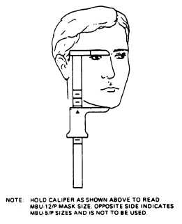
Figure 4-21.—Measuring for proper size of O2 mask.
4-21; measure the distance from the tip of the
bottom surface of the chin to the point of
maximum depression of the nasal root (smallest
part of the upper end of the nose). Once the basic
size has been determined, requisition a new mask
through normal supply channels.
ATTACHMENT OF BAYONET
AND RECEIVER MECHANISM
Before you fit the mask to the helmet, you
should check to see if the MBU-12/P has been
configured to the correct assembly. For complete
information on configuration buildup, refer to
chapter 13 of NAVAIR 13-1-6.7. Once you have
a complete assembly of the right size, you’re ready
to fit the mask to the helmet.
The mask has four mask retaining straps. You
should thread the straps through the slots in the
offset bayonet fittings, as shown in figure 4-22.
Then insert each offset bayonet fitting into a
receiver mechanism to the second locking posi-
tion. When the bayonet is inserted in the receiver,
the first click is caused by the entry of the bayonet
into the entrance of the receiver housing, but it
is not a locking position. There are normally three
clicks when inserting the bayonet to the second
locking position of the receiver. When the bayonet
is in the second locking position, the end of the
bayonet will be approximately even with the outer
Figure 4-22.—Mask retaining straps.
edge of the exit slot on the back of the receiver.
This proper positioning of the bayonet end can
be checked either visually or by passing a finger
over the exit slot on the back of the receiver.
Have the aircrew member place the helmet on
his head and hold the oxygen mask in proper
position on his face.
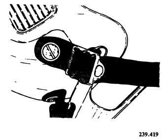
Inspect each receiver mechanism assembly to
be sure that the rotating feature of the device is
locked in its central position. If the rotating
feature is found not to be centered, loosen the two
locking screws on the nameplate of the receiver.
Adjust the receiver until the bayonet is at right
angles to the receiver. Retighten the locking screws
(fig. 4-23).
The receiver has a rotating feature that allows
a 15-degree angle of freedom so that the receiver
can be adjusted slightly in either direction if this
becomes necessary after attachment to the helmet.
Place the receiver on the helmet so that the upper
and lower straps have equal tension. The receiver
should be positioned as close to the edgeroll as
possible
to minimize
bayonet/edgeroll
interference.
With a grease pencil, trace around each
receiver to mark its outline on the helmet (fig.
4-24). You should use this outline to align the
receiver on the helmet. Now remove the helmet
from the wearer and using the back plate of the
receiver as a template, mark the locations for the
four receiver mounting holes on the helmet (fig.
4-25). Remove the earcup assemblies and drill four
mounting holes in the helmet. Do this on each side
by using a No. 25 (0.1495-inch diameter) drill. It
4-28