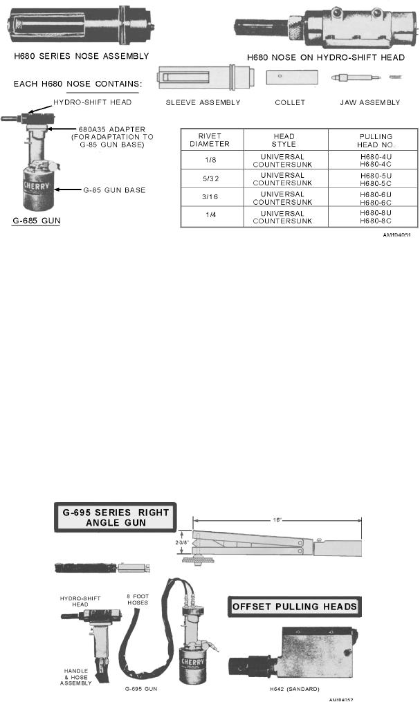
Figure 4-51.--Hydro-shift series gun.
2. Place the jaw assembly in the collet (with the
are preset during manufacture. If further adjustment
spring protruding).
should become necessary, the procedures provided
with the head or in the maintenance manual should be
3. Screw the internal threads of the collet onto the
followed. To install a pulling head of the H615A series,
drawbolt of the hydro-shift head.
engage the threaded portion of the pulling head sleeve
4. Slip the sleeve assembly over the collet.
cap and drawbolt to the gun head and drawbolt. Then
tighten the screws and the jam nut. The pulling head of
5. Place the retainer nut over the sleeve assembly
an H640A series is installed by engaging the internal
and tighten it onto the gun.
threads of the head piston rod. Then align the holes in
Cherrylock rivets require a separate pulling head
the pulling head with those on the gun adapter, and
for each diameter and head style. Each series of gun
tighten one setscrew.
also uses a different set of pulling heads. Refer to the
To install the nose assembly used on the hydro-shift
appropriate operating manual for the proper head for
head equipped gun, shown in figure 4-51, you should
each rivet and gun.
proceed as follows:
There are also special use cherrylock pulling heads,
1. Remove the retainer nut from the hydro-shift
shown in figure 4-52, for use in areas where access is
head.
limited. Since huck and cherrylock rivets are similar,
Figure 4-52.--Special use heads.
4-28

