Pantograph
and/or
hose
with
approved,
nonlubricated swivel. Zerk-type grease fittings in
pantograph swing joints are not authorized,
because of the possibility of contaminating the
fuel with grease.
Dry-break quick-disconnect fuel-service coupling
with a 60- to 100-mesh strainer.
Single-point-pressure refueling nozzle with a 55-
psi maximum pressure regulator.
Fire extinguisher(s) in accordance with NAVAIR
00-80R-14 (minimum of one 150-pound Halon or
TAU unit per fueling point).
Emergency eyewash/shower system available in
the immediate area.
Fire alarm.
MOBILE AIRCRAFT REFUELERS
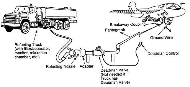
Mobile refuelers are used primarily for cold
fueling operations, with occasional hot-refueling
operations at stations where installation of a direct
refueling system is not justified. If continuous or
extensive hot fueling is being performed with mobile
refuelers, the use of an anchored pantograph, as
shown in figure 7-5, should be considered.
Mobile aircraft refuelers vary in capacity and
configuration. However, whether contractor- or
Government- owned, all mobile aircraft refuelers
have
the
same
basic
requirements.
These
requirements are the following:
Tank construction is one compartment only, with
necessary baffles. Tank must completely drain at
the low point without traps of liquid remaining
in pockets. The tank is designed so that all
portions are accessible for cleaning and
maintenance.
Tank is aluminum or stainless steel.
Tank top opening(s) must be semi-permanently
secured and used only for inventory and for
interior inspections and repairs. Manhole covers
must in-corporate a fusible plug or plugs, each
equipped with fine screens to provide additional
emergency release of vapor.
Tank must be configured for bottom loading. The
bottom loading hardware includes a cutoff valve,
an adapter to accept the standard pressure (SPR)
nozzle, and must be of sufficient size to receive
the product at 600 gallons per minute. A fill
stand anti-driveaway device is incorporated.
Each tank must have an electronic system for
controlling the filling operation (Scully Dynaprobe
or equivalent) that is compatible with the system on
the truck fill stand. It should be located near the
bottom loading adapter and include art anti-
driveaway feature (can be combined with anti-
driveaway device previously mentioned).
The piping system, including all hardware
components, must be capable of dispensing fuel
at the rated flow. A flow diagram of the general
configuration of these system devices is shown in
figure 7-6.
Figure 7-5.—Hot-refueling with truck and pantograph.
7-8