
AFTERBURNER SECTION
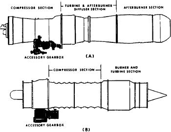
The parts of an axial-flow engine accessory
section are the accessory gearbox and a power
The afterburner increases or boosts the normal
takeoff assembly. These units contain the
thrust rating of a gas turbine engine. There are
necessary drive shafts and reduction gears. Views
times when the maximum normal thrust of an
A and B of figure 1-47 show the location of the
engine is not enough. For instance, it is
accessory gearbox.
conceivable that although the in-flight require-
The accessory gearbox and the power takeoff
ments are met satisfactorily by an engine of
are located near each other. There are two
moderate size, the aircraft still may not have
factors that affect the location of gearboxes in
good takeoff performance. With afterburning,
general. These factors are engine diameter and
maximum thrust is obtained without sacrificing
engine installation.
the economy of the small basic gas turbine.
Designers strive to reduce engine diameter to
Increased thrust is required for takeoff, emergen-
make the engine more streamlined, thereby
cies, and combat conditions.
increasing performance by reducing drag. Also,
engine installation in a particular aircraft may
The afterburner duct replaces the usual air-
dictate the location or rearrangement of the
craft tailpipe. Actually, it is more like a converted
accessory gearboxes.
tailpipe. It functions as the engine tailpipe during
The accessories on engines are the fuel control
nonafterburning (cold) operation and is also the
with its governing device, the high-pressure fuel
main working element of the afterburner. The
pump(s), and a breather screen or other means
entire afterburner is projected from the engine.
for venting the oil system. Other parts are oil
It is supported only at the exhaust end where it
sump, oil pressure and scavenge pumps, auxiliary
is bolted to the engine.
fuel pump, starting fuel pump, and other
accessories, including starter, generator, and
The essential working element of the after-
tachometer. Although these accessories are
burner is an afterburner duct. A flameholder or
essential, the particular combination of engine-
diffuser and a variable-area exhaust nozzle are the
driven accessories depends upon the use for which
other parts (fig. 1-45).
the engine is designed.
The accessories mentioned above (except
The afterburner duct is the main working
starters) are of the engine-driven type. There are
element of the afterburner. It's designed so
the nondriven-type accessories such as booster
that the normal pressure relationship between
coils or ignition exciters, fuel and oil filters,
the air entering the main engine turbine and
barometric units, drip valves, compressor bleed
the air leaving the turbine is not upset. Since
valves, and relief valves.
the duct acts as a burner, the inlet air velocity
must be sufficiently low to support stable
combustion and to avoid excessive pressure
losses. For these purposes a diffuser is located
between the turbine outlet and the tailpipe
burner inlet. Thus, the burner section of the
duct can reduce gas velocities so they do
not exceed the flame propagation rate. Other-
wise, the flame could not get a foothold,
because the onrushing turbine exhaust would
simply push the burning mixture right out
the exhaust nozzle. In addition to the diffuser,
some mechanical mixing of the fuel and air
is necessary. Mixing by diffusion is too slow
a process to be an aid in forming a combustible
mixture.
The flameholders provide local turbulence and
reduce velocity, which aids combustion stability.
The flameholders are located downstream from
Figure 1-47.-Accessory gearbox. (A) Mounted beneath the
the fuel-injection nozzles, thereby allowing time
compressor; (B) mounted beneath the front bearing support.
1-32