
In most centrifugal pumps, the shaft is fitted
with a replaceable sleeve. The advantage of
using a sleeve is that it can be replaced more
economically than the entire shaft.
Mechanical seals and stuffing boxes are used
to seal between the shaft and the casing. Most
pumps are now furnished with mechanical seals;
mechanical seals do not result in better pump
operation but do provide a better environment,
dry bilges, and preservation of the liquid being
pumped.
Seal piping (liquid seal) is installed to cool the
mechanical seal. Most pumps in saltwater service
with total head of 30 psi or more are also fitted
with cyclone separators. These separators use
centrifugal force to prevent abrasive material
(such as sand in the seawater) from passing
between the sealing surfaces of the mechanical
seal. There is an opening at each end of the
separator. The opening at the top is for "clean"
water, which is directed though tubing to the
mechanical seals in the pump. The high-velocity
"dirty" water is directed through the bottom of
the separator, back to the inlet piping for the
pump.
Bearings support the weight of the impeller
and shaft and maintain the position of the
impeller-both radially and axially. Some bear-
ings are grease-lubricated with grease cups to
allow for periodic relubrication.
The power end of the centrifugal pump has
an electric motor that is maintained by you or the
ship's Electrician's Mate.
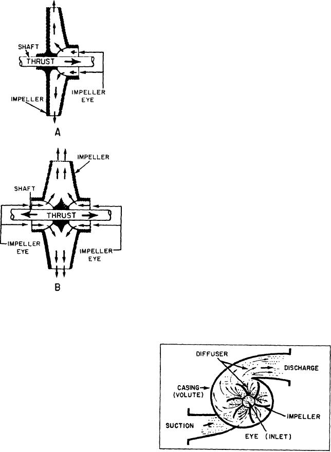
OPERATION.-- Liquid enters the rotating
Figure 7-2.--Centrifugal pump impellers. A. Single-
impeller on the suction side of the casing and
suction. B. Double-suction.
enters the eye of the impeller (fig. 7-3). Liquid
Since an impeller rotates at high speed, it must
be carefully machined to minimize friction. An
impeller must be balanced to avoid vibration. A
close radial clearance must be maintained between
the outer hub of the impeller and that part of the
pump casing in which the hub rotates. The pur-
pose of this is to minimize leakage from the dis-
charge side of the pump casing to the suction side.
Because of the high rotational speed of the
impeller and the necessarily close clearance, the
rubbing surfaces of both the impeller hub and the
casing at that point are subject to stress, causing
rapid wear. To eliminate the need for replacing
an entire impeller and pump casing solely because
of wear in this location, most centrifugal pumps
are designed with replaceable casing wearing rings.
Figure 7-3.--Centrifugal pump flow.
7-3