NOTE: Instead of two separate valves, some
installations use a globe stop-check valve.
With a check valve in the discharge line,
whenever the pressure above the disk rises above
the pressure below it, the check valve shuts. This
prevents liquid from flowing backwards through
the pump.
MAINTENANCE. --You must observe the
operation and safety precautions pertaining to
pumps by following the EOP subsystem of the
EOSS--if your ship has EOSS. If not, use Naval
Ships' Technical Manual and/or the instructions
posted on or near each individual pump. You
must follow the manufacturer's technical manual
o r MRCs for PMS-related work for all
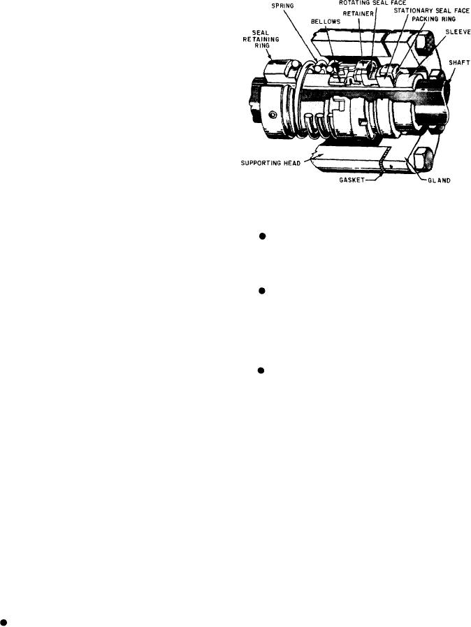
Figure 7-5.--Type-1 mechanical seal.
maintenance work. The MRCs list in detail what
you have to do for each individual maintenance
requirement.
Replace mechanical seals when the seal is
removed for any reason or when the
Mechanical Seals .--Mechanical seals are
leakage rate cannot be tolerated.
rapidly replacing conventional packing as the
means of controlling leakage on centrifugal
Position mechanical shaft seals on the
pumps. Pumps fitted with mechanical seals
shaft by stub or step sleeves. Shaft sleeves
eliminate the problem of excessive stuffing box
are chamfered (beveled) on outboard ends
leakage, which can result in pump and motor
to provide ease of mechanical seal
bearing failures and motor winding failures.
mounting.
Where mechanical shaft seals are used, the
design ensures that positive liquid pressure is
supplied to the seal faces under all conditions of
Do not position mechanical shaft seals by
operation and that there is adequate circulation
using setscrews.
of the liquid at the seal faces to minimize the
deposit of foreign matter on the seal parts.
Fire pumps and all seawater pumps installed
One type of a mechanical seal is shown in
in surface ships are being provided with
figure 7-5. Spring pressure keeps the rotating seal
mechanical shaft seals with cyclone separators.
face snug against the stationary seal face. The
The glands are designed to incorporate two or
rotating seal and all of the assembly below it are
more rings of packing if the mechanical shaft seal
affixed to the pump shaft. The stationary seal face
fails.
is held stationary by the seal gland and packing
ring. A static seal is formed between the two seal
A water flinger is fitted on the shaft
faces and the sleeve. System pressure within the
outboard of the stuffing box glands to prevent
pump assists the spring in keeping the rotating seal
leakage from the stuffing box following along
face tight against the stationary seal face. The type
the shaft and entering the bearing housings.
of material used for the seal face depends on the
They must fit tightly on the shaft. If the
service of the pump. When a seal wears out, it
flingers are fitted on the shaft sleeves instead
is simply replaced.
of on the shaft, ensure that no water leaks under
You should observe the following precautions
the sleeves.
when performing maintenance on mechanical
seals:
Stuffing Box Packing. --Although most cen-
Do not touch new seals on the sealing face
trifugal pumps on gas turbine ships have
because body acid and grease can cause the
mechanical seals, you should be familiar with
seal face to prematurely pit and fail.
stuffing box packing.
7-5

