
oil filling and transfer system where provision
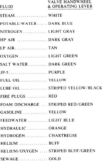
Table 6-1.--Valve Handwheel Color Code
must be made for the transfer of oil from any tank
to any other tank, to the service system, or to
another ship. If, for example, the purpose is to
transfer oil from tank No. 1 to tank No. 4, the
discharge valve for tank No. 4 and the suction
valve from tank No. 1 are opened, and all other
valves are closed. Fuel oil can now flow from tank
No. 1, through the suction line, through the
pump, through the discharge valve, and into tank
No. 4. The manifold suction valves are often of
the stop-check type to prevent draining of pumps
when they are stopped.
VALVE HANDWHEEL
IDENTIFICATION AND
COLOR CODING
Valves are identified by markings inscribed on
the rims of the handwheels, by a circular label
plate secured by the handwheel nut, or by label
plates attached to the ship's structure or to the
adjacent piping.
Piping system valve handwheels and operating
levers are marked for training and casualty
control purposes with a standardized color code.
Color code identification is in conformance with
the color scheme of table 6-1. Implementation of
this color scheme provides uniformity among all
naval surface ships and shore-based training
facilities.
MAINTENANCE
Preventive maintenance is the best way
manufacturer: type of system (oil, water, gas),
to extend the life of valves and fittings.
operating pressure, direction of flow, and other
Always refer to the applicable portion of the
information.
Standard Navy Valve Technical Manual, NAV-
Y o u should also know the operating
SEA 0948-LP-012-5000, if possible. When making
characteristics of the valve, the metal from which
repairs on more sophisticated valve types, use the
it is made, and the type of end connection with
available manufacturer's technical manuals. As
which it is fitted. Operating characteristics and
soon as you observe a leak, determine the cause,
the material are factors that affect the length and
and then apply the proper corrective maintenance.
kind of service that a valve will give; end
Maintenance may be as simple as tightening a
connections indicate whether or not a particular
packing nut or gland. A leaking flange joint may
valve is suited to the installation.
need only to have the bolts tightened or to have
When you install valves, ensure they are
a new gasket or O-ring inserted. Dirt and scale,
readily accessible and allow enough headroom for
if allowed to collect, will cause leakage. Loose
full operation. Install valves with stems pointing
hangers permit sections of a line to sag, and the
upward if possible. A stem position between
weight of the pipe and the fluid in these sagging
straight up and horizontal is acceptable, but avoid
sections may strain joints to the point of leakage.
the inverted position (stem pointing downward).
Whenever you are going to install a valve, be
If the valve is installed with the stem pointing
sure you know the function the valve is going to
downward, sediment will collect in the bonnet and
perform-that is, whether it must start flow, stop
score the stem. Also, in a line that is subject to
flow, regulate flow, regulate pressure, or
freezing temperatures, liquid that is trapped in the
prevent backflow. Inspect the valve body for the
valve bonnet may freeze and rupture it.
information that is stamped upon it by the
6-10