critical/vital circuit or actuating unit requires
flow through the priority valve. A priority valve
1500 psi. When the pressure in the valve reaches
may also be used within a subsystem containing
1500 psi, the poppet reaches the end of its travel.
two or more actuating units to ensure a supply
As the pressure increases, the piston continues to
of fluid to one of the actuating units. In this case,
move to the right, which unseats the poppet and
the priority valve is incorporated in the subsystem
allows flow through the valve, as shown in view
in such a location that the fluid to each actuating
A of figure 6-13. If the pressure drops below 1500
unit, except the critical/vital unit, must flow
psi, the compressed spring forces the piston to the
through the valve.
left, the poppet seats, and flow through the valve
Figure 6-13 shows one type of priority valve.
stops.
View A of figure 6-13 shows the valve in the
Figure 6-13, view B, shows the priority valve
priority-flow position; that is, the fluid must flow
in the free-flow position. The flow of fluid moves
through the valve in the direction shown by the
the poppet to the left, the poppet spring
arrows to get to the noncritical/vital circuits or
compresses, and the poppet unseats. This allows
actuating units. With no fluid pressure in the
free flow of fluid through the valve.
valve, spring tension forces the piston against the
stop and the poppet seats against the hole in the
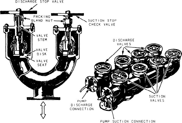
VALVE MANIFOLDS
center of the piston. As fluid pressure increases,
the spring compresses and the piston moves to the
Sometimes suction must be taken from one of
right. The poppet follows the piston, seating the
many sources and discharged to another unit or
hole in the center of the piston until the pre-
units of either the same or another group. A valve
set pressure is reached. (The preset pressure
manifold is used for this type of operation. An
depends upon the requirements of the system and
example of such a manifold (fig. 6-14) is the fuel
is set by the manufacturer.) Assume that the
Figure 6-14.--Valve manifold showing cutaway view of the valves and typical combination of suction and discharge valves.
6-9

